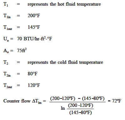
Where δt 1 the temperature difference between hot and cold fluids at one end of the heat exchanger δt 2 the temperature difference between hot and cold fluids at the other end of the heat exchanger.
Counter flow heat exchanger formula.
A heat exchanger can have several different flow patterns.
A counterflow heat exchanger will require less heat exchange surface area than a parallel flow heat exchanger for the same heat transfer rate and the same inlet and outlet temperatures for the fluids.
Lmtd with the correction factor.
The heat exchanger design equation can be used to calculate the required heat transfer surface area for a variety of specified fluids inlet and outlet temperatures and types and configurations of heat exchangers including counterflow or parallel flow.
However the lmtd is valid only for heat exchanger with one shell pass and one tube pass.
The number of transfer units ntu method is used to calculate the rate of heat transfer in heat exchangers especially counter current exchangers when there is insufficient information to calculate the log mean temperature difference lmtd.
In heat exchanger analysis if the fluid inlet and outlet temperatures are specified or can be determined by simple energy balance the lmtd method can.
Counter parallel flow heat exchanger tube length calculation.
Input data in yellow update and reset funtions at bottom of page.
Plane wall heat transfer coefficient u 1 1 ho l k 1 h1.
In the parallel flow arrangement of figure 18 8 a the hot and cold fluids enter at the same end flow in the same direction and leave at the same end.
For multiple number of shell and tube passes the flow pattern.


